
- 6 10-bit analog inputs
- 6 8-bit PWM "analog" outputs
- 6 digital inputs/outputs (partition chosen when component is loaded)
- GPL license statement in source files
Update, 2011-12-05: A user of this script on an Arduino UNO encountered problems where the script would fail sometimes with a Python exception on 'open'. This turns out to be a bug in the Arduino which can be fixed with an update from this thread: http://www.arduino.cc/cgi-bin/yabb2/YaBB.pl?num=1286088093/0, particularly posts 34 and 51.
Update, 2011-12-06: The arduino.py script has been slightly updated so that if some data not produced by the hal.pde sketch is read first, the script does not crash. (this may also be related to UNO boards)
First, load the sketch (firmware source code file) in the Arduino GUI, compile it, and transfer it to the board. The program will remain in the microcontroller's flash rom until it is replaced by another one.
Now, if you don't already have it installed, install python-serial using apt-get or Synaptic Package Manager. (if this command doesn't print an error, python-serial is installed: python -c 'import serial')
Next, copy arduino.py to the name arduino (no extension) in a directory on your PATH. Make it executable: chmod +x bin/arduino
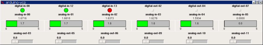
To demo it, in the sample hal script, change the loadusr -W arduino line to reflect the serial port where the arduino is connected. In the directory with the hal file and the pyvcp definition file, halrun arduino-vcp.hal. A control panel should appear which shows the arduino's inputs and allows the outputs to be manipulated.
| Silkscreen Text (Diecimila board) | HAL pin name |
|---|---|
| ANALOG IN 0, 1, 2, 3, 4, 5 | arduino.analog-in-## |
| DIGITAL 2, 4, 7, 8, 12, 13 | arduino.digital-out-## or arduino-digital-in-## |
| PWM 3, 5, 6, 9, 10, 11 | arduino.analog-out-## |
In addition to the standard pins and parameters for digital and analog inputs and outputs, the digital inputs offer the '-pullup' parameter. Setting this to TRUE enables the corresponding weak pull-up built into the AVR microcontroller.
For the analog inputs and outputs, the default gain/scale of 1.0 makes 1V correspond to 1.0. The effective range is thus 0.0 to 5.0.
The items on the 'loadusr' commandline are: the serial port where the Arduino is connected to the PC, and the number of digital I/O pins to use as outputs. The lower-numbered digital pins are outputs, and the higher-numbered pins are inputs. If not specified, these pins are split 3 "in" and 3 "out".
Technical details
The protocol is similar to the earlier revision: 2-byte packets with the top bit signifying "first" or "second" byte. 3-bit address. 11 bit payload. 6 of the 8 addresses are used.For the 6 "input" addresses, the low bits of the payload are an ADC input value. The high bit of the payload is an input pin value.
For the 6 "output" addresses, bits 7..0 of the payload are a PWM output value. Bit 8 is the pin direction, and bit 9 is the pin value (or pull-up enable for inputs).
| Byte | Bit 7 | 6 | 5 | 4 | 3 | 2 | 1 | 0 |
|---|---|---|---|---|---|---|---|---|
| 0 | 1 | address 2..0 | payload 10..7 | |||||
| 1 | 0 | payload 6..0 | ||||||
Files currently attached to this page:
| arduino-vcp.hal | 1.5kB |
| arduino-vcp.xml | 2.5kB |
| arduino.py | 4.2kB |
| halintf.pde | 1.8kB |
(originally posted on the AXIS blog)
Entry first conceived on 25 December 2007, 14:51 UTC, last modified on 15 January 2012, 3:46 UTC
Website Copyright © 2004-2024 Jeff Epler